
My father recently bought a Bridgeport with an EZ Trak II control and installed it in his garage. While the machine itself, mechanically, was in excellent condition and appears to have been rarely used, the control is way out of date. Though more than capable in its day for toolmaker work (small run or one-off parts could be made more easily with quite a bit less hand-cranking) utilizing modern cam and actually getting the G code INTO the control has not been without its challenges.
Among the tasks required to get this machine into production were:
- Modify/rewrite Postprocessor for Autodesk Fusion to accommodate the peculiarities of the control as well as the limitations of the machine itself (for example- no tool changer and no Z axis control)
- 3.5″ floppy drive was replaced by the machine dealer. They chose a GOTEK SFR1M44-U100K Floppy to USB Emulator. This unit, while serviceable, is not user friendly for anyone without a computer background, and requires some management of the disk setup and some screwing around before you can actually use it. In other words, you cant just drop an NC file onto the thumb drive and walk it over to the machine.
- Developing a workflow to make this whole process less painful for daily use.
Post Processor:
A full writeup on post processor editing will be forthcoming eventually, but here are some salient points. A post processor is an interpreter standing between the CAM software and the CNC machine’s control. CAM packages, at least all the ones i’m aware of, do not directly output G Code. Instead, they output coordinates, conditions, tools, feeds, motion types, etc. The CAM software essentially outputs a structured, intermediate set of instructions that the post processor interprets into useable high-level G Code your CNC machine can understand.
Let’s take an example of what happens when you define a contouring operation in CAM:
- In CAM Software:
- The user defines the contouring path and specifies:
- Tool: Tool #1, diameter 6mm.
- Feed rate: 500 mm/min.
- Spindle speed: 1200 RPM.
- The CAM generates toolpath segments:
- Move to
(0, 0, 10)(rapid). - Feed down to
(0, 0, 0). - Contour around a rectangle defined by four corners.
- Move to
- The user defines the contouring path and specifies:
- Intermediate Data: The CAM system represents this as:
{
  "operation": "contour",
  "tool": { "number": 1, "diameter": 6 },
  "spindle": { "speed": 1200, "direction": "CW" },
  "segments": [
    { "type": "rapid", "end": [0, 0, 10] },
    { "type": "linear", "start": [0, 0, 10], "end": [0, 0, 0], "feed": 500 },
    { "type": "linear", "start": [0, 0, 0], "end": [10, 0, 0], "feed": 500 },
    { "type": "linear", "start": [10, 0, 0], "end": [10, 10, 0], "feed": 500 },
    { "type": "linear", "start": [10, 10, 0], "end": [0, 10, 0], "feed": 500 },
    { "type": "linear", "start": [0, 10, 0], "end": [0, 0, 0], "feed": 500 }
  ]
}
3. Post-Processor Translation:
- The post-processor reads this data and converts it into G-code:
N1 G0 Z10
N2 G0 X0 Y0
N3 G1 Z0 F500
N4 G1 X10 F500
N5 G1 Y10
N6 G1 X0
N7 G1 Y0
This is of course a very simplified example. Things get way more complex, especially when you bring in quirky or unusual machines. Also note, the text in the first code block up there is what I would call “json pseudocode,” not literal CAM package output.
CAM packages all use different proprietary structured intermediate data formats, and on top of that, different CAM packages use different methods for post processing. Autodesk (Fusion, HSM for solidworks, Inventor) use Javascript post processors, while mastercam uses its own proprietary scripting model, etc…
Here are some before and after modifications of the post processor I based the custom .CPS file on:
function onLinear(_x, _y, _z, feed) {
  if (pendingRadiusCompensation >= 0) {
    xOutput.reset();
    yOutput.reset();
  }
  var x = xOutput.format(_x);
  var y = yOutput.format(_y);
  var z = zOutput.format(_z);
  var f = getFeed(feed);
  if (x || y || z) {
    if (pendingRadiusCompensation >= 0) {
      pendingRadiusCompensation = -1;
      var d = getSetting("outputToolDiameterOffset", true) ? diameterOffsetFormat.format(tool.diameterOffset) : "";
      writeBlock(gPlaneModal.format(17));
      switch (radiusCompensation) {
      case RADIUS_COMPENSATION_LEFT:
        writeBlock(gMotionModal.format(1), gFormat.format(41), x, y, z, d, f);
        break;
      case RADIUS_COMPENSATION_RIGHT:
        writeBlock(gMotionModal.format(1), gFormat.format(42), x, y, z, d, f);
        break;
      default:
        writeBlock(gMotionModal.format(1), gFormat.format(40), x, y, z, f);
      }
    } else {
      writeBlock(gMotionModal.format(1), x, y, z, f);
    }
  } else if (f) {
    if (getNextRecord().isMotion()) { // try not to output feed without motion
      forceFeed(); // force feed on next line
    } else {
      writeBlock(gMotionModal.format(1), f);
    }
  }
}
became:
function onLinear(_x, _y, _z, feed) {
  if (pendingRadiusCompensation >= 0) {
    xOutput.reset();
    yOutput.reset();
  }
  var x = xOutput.format(_x);
  var y = yOutput.format(_y);
  var f = getFeed(feed); // Format the feed rate
  if (x || y) { // Only check for x and y, ignoring z
    if (pendingRadiusCompensation >= 0) {
      pendingRadiusCompensation = -1;
      var d = getSetting("outputToolDiameterOffset", true) ? diameterOffsetFormat.format(tool.diameterOffset) : "";
      writeBlock(gPlaneModal.format(17));
      switch (radiusCompensation) {
        case RADIUS_COMPENSATION_LEFT:
          writeBlock(gMotionModal.format(1), gFormat.format(41), x, y, d, f);
          break;
        case RADIUS_COMPENSATION_RIGHT:
          writeBlock(gMotionModal.format(1), gFormat.format(42), x, y, d, f);
          break;
        default:
          writeBlock(gMotionModal.format(1), gFormat.format(40), x, y, f);
      }
    } else {
      writeBlock(gMotionModal.format(1), x, y, f); // Output only x, y, and feed
    }
  } else if (f) {
    if (getNextRecord().isMotion()) { // Try not to output feed without motion
      forceFeed(); // Force feed on the next line
    } else {
      writeBlock(gMotionModal.format(1), f); // Output feed alone
    }
  }
}
On examination, you will notice the absence of
var z = zOutput.format(_z);
as well as removal of all references to the Z coordinate in lines likewriteBlock(gMotionModal.format(1), gFormat.format(41), x, y, z, d, f);
writeBlock() is what actually generates a line of output to the G Code file. I removed references to Z in the output of the onLinear() function because the target machine has no motor moving the Z axis- the Z axis is manually controlled. In addition to removing the Z from linear moves (G1 toolpaths), I added an M0 (program stop) to any other Z moves output by the post processor by altering the following line:
var zOutput = createOutputVariable({onchange:function() {state.retractedZ = false;}, prefix:"Z"}, xyzFormat);became:
var zOutput = createOutputVariable({ onchange: function () { state.retractedZ = false; }, prefix: "M0Z" }, xyzFormat);The only change required was modifying the prefix. The prefix is the letter assigned to the structured intermediate data representing that movement or function. The prefix “Z” is applied to all Z moves, like G1 Z-5.0 for example. Changing the prefix “Z” to “M0Z” adds a program stop to allow the machinist to move the z to the appropriate height before the control moves to the next block.
GOTEK Emulator
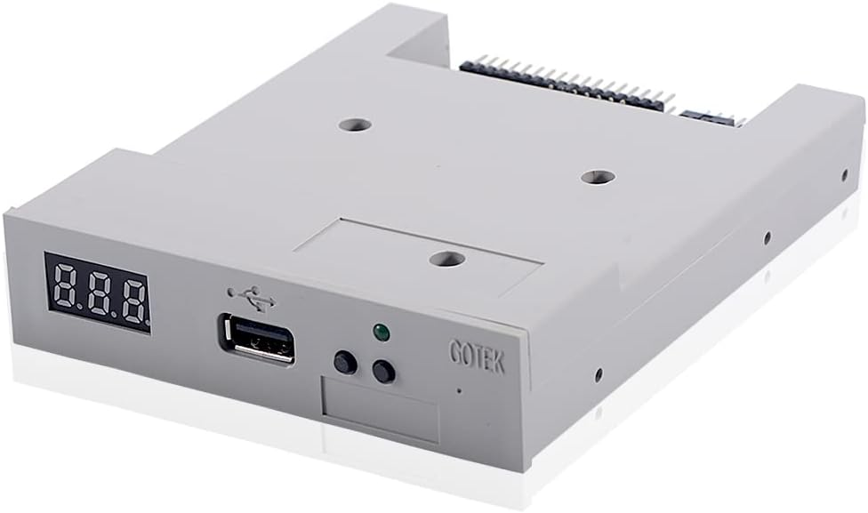
The Floppy emulator installed in the machine looks similar to the one pictured above, made by GOTEK. Simply put, it is a device designed for old or aging computerized equipment that were built using a 3.5″ floppy drive as a means for loading data, programs, user files, etc. They are commonly found on industrial equipment, such as CNC machines, computerized sewing machines, data loggers for older PLC’s and so on. They are also used commonly as replacements for floppy drives in musical instruments from the 80’s and 90’s like synthesizers, keyboards, and samplers.
In a nutshell, here’s how they work:
- Download and install the software from the GOTEK site. The software reformats your USB thumb drive as a bank of individually partitioned virtual floppy disks. You define how many and what size.
- Put the thumb drive in your computer, reformat it as mentioned, and move the files you want to load on the target machine into one of the virtual floppy disk partitions. They are numbered 000 through 099 if you formatted it to make 100 “disks”
- Select which disk you want to load on the emulator before putting the thumb drive in. The disk is selected using the two buttons on the face of the emulator.
- After inserting the thumb drive, the emulator reads the selected partition and loads it into memory on the emulator itself, which the machine sees as a single floppy disk.
- Proceed as normal with the function of the equipment.
There are other brands of emulator, but these are the most ubiquitous, based mostly on their price point. They are not, however, the easiest to deal with. There are other brands, the best of which is Shop Floor Automation, which you can google if you’re interested. They are MUCH easier to work with, and operate in the drag-and-drop manner most people are used to, without all this partitioning and special software. They are an order of magnitude more expensive, around $400-$500 instead of $30 for the cheaper, clunkier GOTEK unit.
Below is a short video outlining the process for loading a program onto the control following the basic steps outlined above. Good Luck!