
Macro Programming on the Haas CNC Control
Macro programming comes in handy on occasion as a technician testing a machine tool during or after troubleshooting or repair. For a machinist producing small production runs, rapid prototyping, or handcoding NC programs on a PC or right at the control, it is equally useful, if not more so.
Here are two example programs written for different purposes. The first is functional, implementing a counter and some macro variable arguments to M6 with the aim of cycling through the entire tool changer carousel. This is done after a repair to the tool changer when the problem the customer was experiencing was intermittent. After running this for a period of time, maybe while cleaning up after putting everything back together, you can tell the customer “I ran 153 consecutive tool changes without issue, I’m confident the problem is solved.”
The second program is more academic, the purpose of which is to have the CNC machine trace out an ellipse (oval) of specific dimensions, defined by the user as 2 macro variables, the major radius (half the largest possible chord through the center of the ellipse) and the minor radius (half the smallest possible chord through the center of the ellipse.)
Below is the code, additional explanation will be afterwards. My github has some other content you may find interesting if you work in this field.
Brief Overview of Macro Useage:
Macro variables 1-31 are “local variables” meaning they can be used temporarily within a program for things like calculation, placeholding, or outputting the results of a calculation as an argument to a G or M code. For example, instead of writing:
G0 G90;
G54;
G1 F200. X5.0;
You could write:
G0 G90;
G54;
G1 F200. X#1;
… and move the x axis to whatever value is stored in macro variable #1. Storing a value in that variable can be easily done by issuing a command like:
#1 = 5.0
or…
#1 = #3 + #9
… to add together the value of two previously defined variables. If you scan through the program, you will see how this may be useful to automate some tasks rather that type them all out explicitly, especially when done strictly at the control.
Tool Changer Cycle Test:
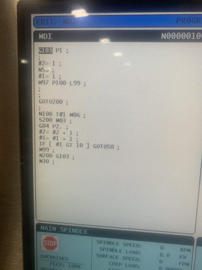
%
O01008
(TOOL CHANGER TEST PROGRAM)
((C) MICHAEL DILLIO FOR PRAXIS MECHATRONICS 2023)

(---------OPTIMIZED FOR HAAS CONTROL-------)
(RUNS THROUGH ALL TOOLS IN THE TOOL CHANGER, TESTING FOR)
(ORIENTATION AND PROPER FUNCTIONING OF SMTC OR UMBRELLA.)
(#1 IS THE CURRENT TOOL, #2 IS A COUNTER OF TOTAL)
(TOOL CHANGES PERFORMED. #3 STORES HOW MANY TOOLS AVAIL:)
(#3 = 10 FOR A SMALL UMBRELLA, 40 FOR BIG SMTC, ETC.)


G103 P1


#3 = 24 (TOTAL NUMBER OF TOOLS IN CAROUSEL)
#2 = 1 (SET COUNTER TO 1)

N50 (OUTER LOOP START)
#1 = 1 (SET INITIAL TOOL TO 1)
M97 P100 L99 (BEGIN INNER LOOP BY CALLING LINE 100)

GOTO200 (99 OUTER LOOPS COMPLETED)

N100 T#1 M6
S200 M3
G4 P2.
#2 = #2 + 1 (INCREMENT COUNTER)
#1 = #1 + 1 (INCREMENT TOOL #)
IF [ #1 GT #3 ] GOTO50 (TEST FOR LAST TOOL)
(IF ALL TOOLS HAVE CHANGED, RESTART OUTER LOOP AT N50)
M99 (RETURN TO M97 LINE: CHANGE TO NEXT TOOL)
N200 G103 (RESUME LOOKAHEAD)
M30
For the tool changer test program, if you had just a 10 pocket tool changer, the idea of typing it out explicitly at the control is not daunting. It would be simply:
T1 M6;
T2 M6;
T3 M6;
...
T10 M6;
M99;
… where M99 loops the program from the beginning. Now, theres no counter, so you’d be guessing how many tool changes you did in total. You could stand there and count the loops, then multiply that number by 10, but that takes a shit all over the whole concept of automation- let the computer get things done by itself while the human does something else.
So, lets step through the program one chunk at a time. There is the opening code (% sign and program number required or the control will throw an alarm), followed by a block of comments. Comments are there for the user as basic instructions on setup or use of the program, and are not read by the control. Anything surrounded by (parenthesis) is a comment. They are useful, you should use them if you plan on saving a program for later.
The first actually executed line is the G103 P1. This code (G103) is “Block Lookahead.” When a CNC machine, especially a modern one, is running a program, its is actually processing the code way ahead of the block it is currently executing. It needs to be able to do this so it can see sharp changes in direction and aggressive accelerations coming up. Thats how it can navigate the geometry smoothly without having to stop and sit and think about it, thereby fucking your part up. This is useful for machining, but bad for calculation, as it will do all the math calculation (macro calculation) way ahead of time, and way before a tool change is done.
G103 P1 limits the lookahead to 1 block of code, i.e. do the math one step at a time.
The next two lines are some definitions, changed by the user of the program. The comments next to the lines explain them. After that, we have N50, which begins the outer loop. “N50” itself is just a line number, essentially a label for that spot in the program. When we want the program to jump back to that spot, we will command GOTO50. You will see that a few lines down.
Next, we set the counter to 1. If, for example, you ran 53 tool changes and had to stop in the middle, and you wanted the final count to be accurate, you could change this to 53 so the counter starts from the point you left off. Starting from scratch, we will leave it at 1.
After that we have the perhaps confusing line M97 P100 L99. This means “make the program jump (M97) to line number 100 (P100) and then loop 99 times (L99).”
The next few blocks are incrementing the counter variable after executing each tool change. It checks to see when we are at the limit of the size of the carousel (can’t change to tool 25 if there are only 24 pockets) with the line:
IF [ #1 GT #3 ] GOTO50 (TEST FOR LAST TOOL)
This is an “if” statement, used to control the flow of a macro program by testing a variables numerical value against a conditional statement like the one above. We use [square brackets] to trap a mathematical expression and to enforce order of operations. You will see more of that in the oval program. Basically, in this statement we’re checking to see if #1 (current tool) is greater than #3 (total number of tool pockets available) and if so, it exits the loop, and resets back to tool 1, and continues the loop, each time adding to the overall tool change count stored in variable #2. You can change to the macro variable list screen while the program is running, so you know where it is when you finally decide to stop the loop.
User-defined Ellipse Macro:
This program is a bit more complicated. It involves solving the mathematical function for an ellipse:
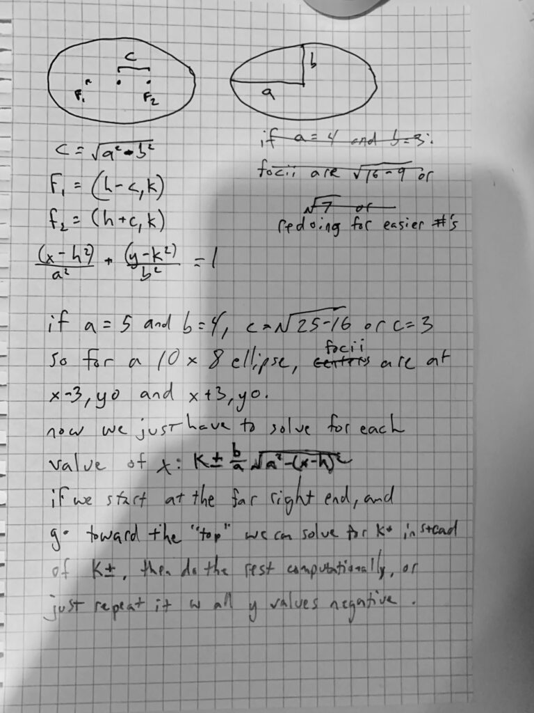
Its always best to sketch up a complicated idea on paper, and prove it out with actual example numbers, so you can step through it in your mind before trying to shoehorn it into the domain of as limited a programming paradigm as G code.
On paper here, I wrote out a few expressions defining the geometry of an ellipse, which you can find plenty of writeups about online. Most of the problems we run into with 3 axis machining are limited to pretty standard cartesian geometry, all of which is covered very well on websites designed for high school kids in precalculus.
Here is the code:
%
O01009
(ELLIPSE MACRO CHC)
((c)Michael Dillio for Praxis Mechatronics 2024)

(---------OPTIMIZED FOR HAAS CONTROL-----------)

(THIS PROGRAM TAKES THREE INPUT VARIABLES AND RUNS A)
(SUBROUTINE THAT TRACES OUT AN ELLIPSE WITH THE DIMENSIONS)
(OUTLINED IN VARIABLES #1 AND #2. )
(TO ADJUST THE SIZE OF THE ELLIPSE, ADJUST THOSE VARS)
(#3 IS THE "RESOLUTION" VARIABLE.)
(THE PROGRAM STEPS THROUGH VALUES FOR X AT #3 INTERVALS)
(AND SOLVES FOR Y WITH EVERY INTERVAL)

#1= 7.0 (MAJOR RADIUS 'A')
#2= 1. (MINOR RADIUS 'B')
#3= 0.01 (SEGMENT SIZE IN X)

(CALCULATE CENTER OFFSETS FOR F1 AND F2, KNOWN AS 'C')
#4= SQRT[ [ #1 * #1 ] - [ #2 * #2 ] ] (C)
#5= 0 - #4 (F1)
#6= 0 + #4 (F2)

(MOVE TO FAR RIGHT:)
G54 G00 X0 Y0 (CENTER OF ELLIPSE)
G00 X#1 (FURTHEST RIGHT POINT, Y STAYS AT 0)
G01 F100.

#10= #1
N100
(RUN FUNCTION ITERATING PER #3 SIZE)
#7= #2 / #1 (B/A)
#8= #10 (X-H)
#9= SQRT[ [ #1 * #1 ] - [ #8 * #8 ] ]
#11= #7 * #9
G01 X#10 Y#11
#10= #10 - #3
IF [ #10 GE [ 0 - #1 + #3 ] ] GOTO100

N200
(BACK THE OTHER WAY)
#7= #2 / #1 (B/A)
#8= #10 (X-H)
#9= SQRT[ [ #1 * #1 ] - [ #8 * #8 ] ]
#11= #7 * #9
G01 X#10 Y[0 - #11]
#10= #10 + #3
IF [ #10 LE [ #1 - #3 ] ] GOTO200


(#10 = CURRENT X)
(#11 = CURRENT Y)
%
This program is 54 lines of G code that will define 1000’s of points in XY 2 dimensional space, limited only by the size of the ellipse you defined and the resolution of the machine tool used to machine it (in this case, 0.0001″)
The following lines are the only lines needing adjustment from the operator:
#1= 7.0 (MAJOR RADIUS 'A')
#2= 1. (MINOR RADIUS 'B')
#3= 0.01 (SEGMENT SIZE IN X)
#1 and #2 were explained in the opening of this article, and #3 is the segment size, or the “resolution.” In this example, it is set for 0.01, or 0.0100″ stepover in X for every change calculated in Y. This would result in a rather jagged looking ellipse. A realistic value for this parameter would be .002″ or .0001″ if you had all day to let the program run. In a real use-case environment, I’d rough the shape out slightly oversize at .010 resolution, then finish it at .0005.
This program, however, is purely academic in nature, and anyone wishing to machine an ellipse is better off firing up the CAM software. Unless there’s something seriously wrong with you.